
Description
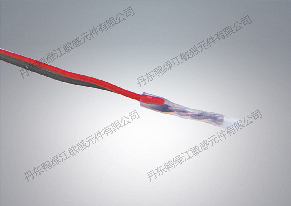
The thermocouple temperature sensor has a simple structure, fast thermal response, convenient installation, wide temperature measurement range, and good stability. Output thermoelectric potential signal for temperature detection.
The principle of using a thermocouple to measure temperature is that a thermocouple is composed of two different components of conductors connected at both ends to form a circuit. When the temperature of the junction is different, an electromotive force will be generated in the circuit, which is called the thermoelectric effect, and this electromotive force is called the thermal electromotive force. The generated thermoelectric potential varies with temperature, so the level of thermoelectric potential can represent the level of temperature. According to this principle, different types of thermocouples can be made.
Technical parameters
Graduation number | Temperature measurement range | )Allowable deviation (℃) | Insulation resistance |
J | 0℃~500℃ | ±0.75%t | DC500V≥100MΩ |
K | 0℃~1200℃ | ±0.75%t | |
E | 0℃~750℃ | ±1.5%t | |
T | -200℃~350℃ | ±0.75% |
Temperature(℃) | Standard value of thermoelectric electromotive force(μV) | |||
J couple | K couple | E couple | T couple | |
| 0 | 0 | 0 | 0 | 0 |
| 10 | 507 | 397 | 591 | 391 |
| 20 | 960 | 798 | 1192 | 790 |
30 | 1537 | 1203 | 1801 | 1196 |
| 40 | 2059 | 1612 | 2420 | 1612 |
| 50 | 2585 | 2023 | 3048 | 2036 |
| 60 | 3116 | 2436 | 3685 | 2468 |
| 70 | 3649 | 2851 | 4330 | 2909 |
| 80 | 4187 | 3267 | 4985 | 3358 |
| 90 | 4726 | 3682 | 5648 | 3814 |
| 100 | 5269 | 4096 | 6319 | 4279 |
| 120 | 6360 | 4920 | 7685 | 5228 |
| 140 | 7458 | 5735 | 9081 | 6206 |
| 160 | 8562 | 6540 | 10503 | 7209 |
| 180 | 9669 | 7340 | 11951 | 8237 |
| 200 | 10779 | 8138 | 13421 | 9288 |
Model Example:WR-JMB1-206
WR | Thermocouple sensor |
| J | J~Jcouple K~Kcouple E~Ecouple T~Tcouple |
| M | Bearing temperature measurement |
| B | B metal protective sleeve C plastic protective sleeve D composite protective sleeve |
| 1 | 1 adjustable 2 fixed 3 right angle adjustable 4 right angle fixed |
| 206 | 1 without fixed device 2 with fixed device 06 temperature measurement end Φ six |
Ordering Example:WR-JMB1-206/90-M12×1-900-M14×1.25-P2×1000
| 90 | Installation hole depth |
M12×1 | Temperature measuring end thread |
| 900 | Length of protective sleeve |
| M14×1.25 | Terminal thread |
| P | Shielded wire |
| 2×1000 | Two wire system × Line length |
Installation method
When used for winding temperature measurement, a winding temperature thermocouple is selected. The thermocouple is installed inside the winding, and the lead wire is led out of the motor and connected to the motor's junction box. When used for bearing temperature measurement, bearing temperature thermocouples are selected. Drill holes in the bearing chamber according to the thread matching size, hinge the corresponding internal threads, and ensure reliable contact between the temperature measurement end face and the bearing. Do not let the sensor lead bear excessive tension, and pay attention to grounding the shielding wire.


 QQ
QQ Speed-dial
 Follow WeChat